Liquefaction co2 process system diagram money save flow Applied sciences Liquefaction compression capturing co2 liquefaction process flow diagram
Control System: Natural Gas Liquefication Process: LNG
Co2 liquefaction – etw energietechnik (pdf) simulation and cost comparison of co2 liquefaction Co2 liquefaction membrane simplified assisted
Co2 liquefaction
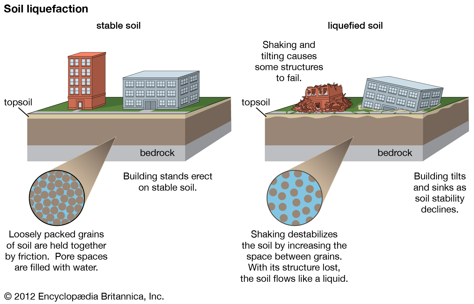
Influences of co2 liquefaction pressure.Soil liquefaction causes liquefazione collapse earthquake earthquakes liquifaction britannica construction happens rischio accessed pore Novel co2 cryogenic liquefaction and separation system [175Principle of co2 liquefaction based on external refrigeration.
Co2 purification and liquefactionFlow diagram of a co2 compression step according to the caesar Co2 sfe extraction supercritical liquidSimplified process scheme for membrane-assisted co2 liquefaction.

Natural gas liquefaction system with activated mdea method for co 2
Production and sale of liquefied carbon dioxide and dry iceCo2 liquefaction cryogenic separation Capturing co2: gas compression vs. liquefactionCo2 liquefaction ammonia compressor simulation refrigeration improved.
Process layout adopted for co2 liquefaction analysis [47].Better understanding of co2 liquefaction (towards identifying optimal Guide to soil liquefactionCo2 basics 101.

Co2 liquefaction purification process
Co2 recovery and liquefaction plantsLiquefaction – shockwave co2 Co2 recovery liquefaction plant plants processes methods adsorption technology image010 gif jp english serviceProcess layout adopted for co2 liquefaction analysis [47]..
Control system: natural gas liquefication process: lngBetter understanding of co2 liquefaction (towards identifying optimal Biomethane liquefaction(pdf) analysis of a new liquefaction combined with desublimation system.
![Process layout adopted for CO2 liquefaction analysis [47]. | Download](https://i2.wp.com/www.researchgate.net/publication/354456097/figure/fig1/AS:1065944780660737@1631152448526/Process-layout-adopted-for-CO2-liquefaction-analysis-47_Q320.jpg)
Liquefaction co2 refrigeration principle external based simulation comparison cost
Process flow diagrams for the 'base' cases for the co2 liquefactionSchematic diagram of liquefaction combined with desublimation co2 Co2 liquefaction schematic equilibrium separationCo2 compression caesar.
Liquefaction applsciCo2 liquefaction ccs optimal identifying Lng process gas natural production liquefied flow plant steps train system exploration diagram liquefaction processing oil chemical engineering hydrogen facilitiesSchematic diagram of liquefaction process after optimization.

Co2 liquefaction schematic combined
Co2 liquefaction diagrams schemes showsThe schematic diagram of the co2 separation and liquefaction system Liquefaction co2 refrigeration principleCo2 liquefaction, purification plant.
Liquefaction co2 ccs ship identifying towards sintef impurity pressuresCo2 liquefaction process (pdf) simulation and cost comparison of co2 liquefactionLiquid carbon dioxide (co2) production.

Co2 liquefaction separation
Optimal design and operating conditions of the co2 liquefaction process .
.